


Key takeaways
• A CAN-connected gauge reads data broadcast on the vehicle’s CAN bus (usually SAE J1939) instead of a dedicated analog sender wire.
• One CAN connection can carry dozens of parameters, so wiring gets simpler and diagnostics get deeper.
• Analog gauges are not obsolete. They still suit simple, cost-sensitive machines with no CAN bus.
• In 2026 the topics that matter most are J1939 diagnostics inside the gauge, the slow arrival of CAN FD (J1939-22), gauge cybersecurity, EV and hydrogen displays, and India’s emissions, ADAS and tracking rules.
• "CAN compatible" is not a specification. Confirm protocol, baud rate, PGN and SPN mapping and error handling before ordering.
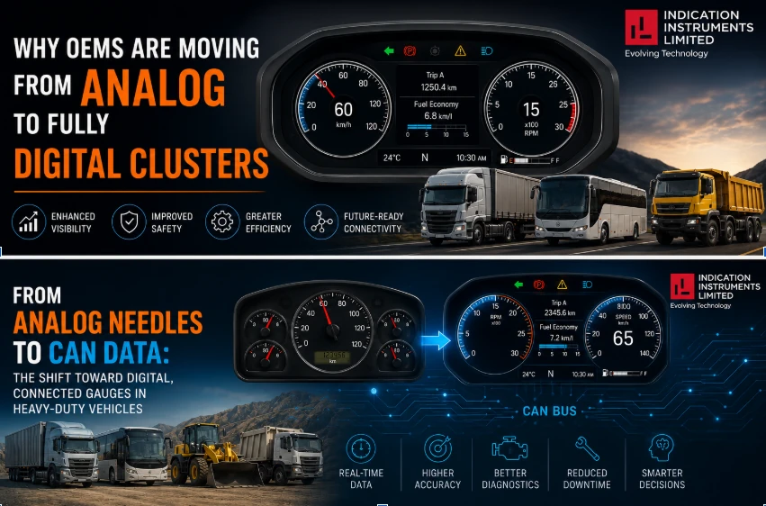
For decades, a needle sweeping across a dial was how a truck driver knew engine temperature, fuel level or RPM. That is changing. Heavy-duty vehicles such as trucks, buses, gensets and construction equipment increasingly read these same parameters from a CAN bus and show them on connected digital gauges rather than mechanical pointers.
This guide explains how a CAN-connected gauge actually works, why the shift is happening now, what has changed in 2025 and 2026, and how to specify the right gauge for your next OEM program. It is written for design engineers, purchasing teams and fleet technical managers.
What Is the Difference Between an Analog Gauge and a Digital, CAN-Connected Gauge?
An analog gauge reads a physical signal directly, such as a sender unit’s resistance or a mechanical pressure line, and moves a needle in proportion. A digital, CAN-connected gauge instead reads data broadcast over the vehicle’s CAN bus, often using the SAE J1939 protocol, and displays it through a stepper-motor pointer, LCD readout or bar graph. The needle can look identical. The architecture behind it is completely different, and far more capable.
| Analog gauge | Digital, CAN-connected gauge | |
| Signal source | Sender unit or mechanical line wired to that one gauge | Data broadcast on the CAN or J1939 bus by the ECU |
| Wiring | One sender and wire per gauge | One CAN connection can carry many parameters |
| Diagnostics | Needle or a separate warning lamp | Can decode fault codes and thresholds and show them on the gauge |
| Calibration | Often fixed to a specific sender curve | Often configurable for pulse and threshold settings |
| New fuel types (EV, hydrogen) | Needs new senders and new dials | Can be reprogrammed to show state of charge, motor temperature or tank pressure |
| Best fit | Simple, cost-sensitive machines without a CAN bus | Vehicles that already run CAN or J1939 for engine, transmission or telematics |
How Does a CAN-Connected Gauge Actually Work?
Understanding the signal path makes it much easier to specify and troubleshoot a gauge. In a J1939 vehicle it works like this:
1. The ECU measures the value. The engine or transmission control unit reads its own sensors, such as coolant temperature or engine speed.
2. The ECU broadcasts it. The value is sent on the bus inside a message called a Parameter Group (PGN). Each PGN carries one or more individual data points called SPNs (Suspect Parameter Numbers).
3. The gauge listens. The gauge is configured to pick out the specific PGNs and SPNs it needs. It does not have to be wired to the sensor.
4. The gauge converts the raw value. Each SPN has a defined resolution and offset, so the gauge scales the raw number into a real unit such as °C, kPa or rpm.
5. The gauge shows the result. A stepper motor moves the pointer, or an LCD or bar graph updates.
6. The gauge handles problems. J1939 reserves special values to mean "error" or "not available", and a good gauge also reacts sensibly if messages stop arriving, instead of freezing on the last value.
A few terms worth knowing:
• CAN 2.0B: the communication layer that carries data frames, using 29-bit extended identifiers in J1939.
• SAE J1939: the standard built on CAN for trucks, buses, tractors, gensets and construction machinery. It defines what each message means.
• PGN and SPN: the message type and the individual data point inside it.
• DM1: the diagnostic message that carries active fault codes and warning-lamp status.
• Baud rate: the bus speed. J1939 has traditionally run at 250 kbit/s, and some networks use 500 kbit/s, so the gauge must match the vehicle.
Why Are Heavy-Duty Vehicles Moving Toward CAN-Based Gauges?
The instrument cluster market as a whole is moving from traditional analog clusters to digital formats. For heavy-duty and off-highway vehicles, CAN-based gauges solve a problem analog wiring cannot: a single CAN bus can carry dozens of parameters, such as fuel, DEF or AdBlue level, engine hours and fault codes, over one connector instead of a dedicated wire and sender for every gauge. That simplifies harnesses and improves diagnostic depth at the same time.
Engine electronics have also become the norm. Modern diesel engines are ECU-controlled to meet emission rules, so the data already exists on the bus. In India, BS6 Phase 2 (from April 2023) brought advanced on-board diagnostics (OBD-II) for real-time monitoring of emission-related faults, and construction equipment now follows CEV Stage V emission norms aligned with EU Stage V. Once an engine ECU is broadcasting this data, reading it on a gauge is cheaper and more informative than adding separate analog senders.
What Has Changed Recently: Trends Shaping Digital Gauges in 2026
1. Diagnostics are moving onto the gauge itself
The J1939-73 standard defines around 60 diagnostic messages for reporting, repair and compliance in heavy-duty vehicles. The most familiar is DM1, which carries the status of the warning lamps and any active fault codes, each described by an SPN (what failed) and an FMI (how it failed). A gauge that decodes DM1 can show a fault directly on the dial or display instead of relying only on a separate warning light. That gives the operator earlier, more specific information.
2. CAN FD (J1939-22) is arriving, gradually
J1939-22 brings CAN FD to J1939, allowing larger frames (up to 64 bytes) and higher data rates. The standard was published in 2021, and industry sources describe the transition as underway but gradual. Early use is expected in data-heavy areas such as emissions-heavy engines and hybrid or electric powertrains, often with a new CAN FD network running alongside classic J1939. For gauge buyers the practical point is simple: today’s programs still run classic J1939, but a long-life platform should ask suppliers about their CAN FD roadmap.
3. Cybersecurity has reached the gauge
J1939 was designed for a closed vehicle network and has no native authentication or encryption, which leaves it open to spoofing and replay attacks in a realistic threat model. For new vehicle types, regulations such as UNECE R155 require cybersecurity management, and industry sources report that India’s AIS-189 applies to new vehicle types from October 2025. A gauge that only listens on the bus carries much less risk than a device that also transmits. Ask your supplier whether the gauge transmits, what it can change on the bus, and how it is protected against tampering.
4. Electrification and hydrogen change what gauges show
Battery-electric gensets and hydrogen-powered machines need state of charge, motor temperature, DC bus voltage or tank pressure, none of which map to a traditional fuel or coolant dial. A reprogrammable CAN-connected gauge can show these without changing the hardware. Industry commentary also warns that electric platforms may use OEM-specific message definitions rather than the standard J1939 catalog, so always confirm the exact PGN and SPN list with the vehicle maker before you finalise the gauge.
5. India’s ADAS and safety rules put more alerts in front of the driver
MoRTH’s GSR 184(E) package covers buses and trucks (M2, M3, N2 and N3) and includes emergency braking (AIS-162), driver drowsiness and attention warning (AIS-184), blind spot and moving-off information (AIS-186, AIS-187) and lane departure warning (AIS-188). Industry sources report 1 April 2026 for new models and 1 October 2026 for existing models, and dates have shifted before, so check the current notification. Most of these are alerting systems, which means the cluster or gauge has to show their warnings clearly. See our guide to how Driver Information Systems improve vehicle safety and comfort.
6. Telematics and vehicle health monitoring
Fleet operators increasingly combine CAN data with tracking. In India, AIS-140 tracking devices are required for public transport vehicles, and integrating CAN, OBD and J1939 data into vehicle health monitoring is part of that picture. The same CAN data that drives the gauge can feed telematics, which is another reason to standardise on CAN-connected instrumentation.
7. Proprietary message definitions
Some OEMs use proprietary PGN and SPN encoding, especially for telematics and electric powertrains. A gauge that supports "J1939" in general may still not show a proprietary parameter. This is why field-configurable settings and a clear parameter list from the OEM matter so much.
Are Analog Gauges Becoming Obsolete?
Not entirely, and OEMs should not assume digital is automatically right everywhere. Simple, cost-sensitive applications such as basic gensets or entry-level construction equipment still use mechanical temperature and pressure gauges effectively. They do not need CAN integration, and they are cheaper to source and service. The shift toward digital is strongest where the vehicle already has a CAN bus for other systems such as the engine ECU, transmission or telematics. At that point, tapping into existing CAN data for gauges is more efficient than running separate analog sender wiring. For a fleet-level view of this choice, read J1939 gauges vs analog gauges: which one does your fleet actually need.
What Are the Practical Benefits of CAN-Connected Gauges for Fleet Operators?
1. Fewer wiring failures. One CAN connection replaces multiple analog sender wires, a common failure point in vibration-heavy environments.
2. Richer diagnostics. Fault codes and threshold warnings can be built into the gauge display itself, not just a separate warning light.
3. Easier calibration. Pulse and threshold settings can often be configured in the field rather than requiring gauge replacement.
4. Consistent data across the dashboard. A CAN-connected gauge and a digital display can show the same underlying data without duplicate sensors.
5. Faster fault-finding. When the gauge shows an SPN and FMI, technicians know where to start instead of guessing.
How Should OEMs Decide Between Analog and Digital Gauges?
The decision usually comes down to three questions. Does the vehicle already run a CAN 2.0B or J1939 bus for other systems? Does the application need reprogrammable thresholds or multi-parameter display, such as a combined fuel and hour meter? And does the OEM need field-level diagnostic data, not just a dashboard reading? If the answer to any of these is yes, a CAN-connected digital gauge is usually the better long-term choice, even if the upfront unit cost is slightly higher than an analog equivalent.
| Application | Usually best | Why |
| Basic genset, no ECU data | Analog | Lowest cost, no CAN needed |
| Entry-level construction equipment | Analog or mixed | Cost-driven; use digital only where CAN exists |
| Truck or bus with a J1939 engine ECU | CAN-connected digital | Data is already on the bus; diagnostics add value |
| Fleet with telematics and health monitoring | CAN-connected digital | Shared data across gauge and telematics |
| Battery-electric or hydrogen equipment | CAN-connected digital | Needs new parameters, reprogrammable display |
| Long-life platform | CAN-connected, with a CAN FD roadmap | Protects against future network changes |
What Should OEMs Verify Before Specifying a Digital Gauge Supplier?
1. Exact protocol support. Confirmed support for the protocol in use (CAN 2.0B or J1939), not just "CAN compatible" on paper.
2. Baud rate and parameter list. Match to your bus, and get the list of PGNs and SPNs the gauge decodes.
3. Error and timeout behavior. What the gauge shows when data is "not available", in error, or when messages stop.
4. Test evidence. ISO 16750 compliance with documented test reports for the electrical, mechanical (vibration) and climatic (temperature and humidity) loads that apply, plus the IP rating for dust and water.
5. EMC performance. Documented electromagnetic compatibility results for your vehicle type.
6. Field configuration. Configurable pulse and threshold settings to avoid re-ordering hardware for calibration changes.
7. Supply range. Voltage range that covers your 12 V or 24 V system.
8. Product range and lifecycle. A supplier that offers both analog and digital gauge lines, so simpler applications are not over-engineered, and a clear plan for long-term availability and CAN FD.
Common Integration Mistakes to Avoid
• Assuming "CAN compatible" means J1939. The gauge and the ECU must speak the same protocol and use the same parameter definitions.
• Wrong baud rate or poor bus termination. These cause intermittent or no data and are often mistaken for a faulty gauge.
• Ignoring scaling. Each SPN has its own resolution and offset. A wrong scale gives a plausible but incorrect reading.
• Not testing the no-data case. Unplug the ECU or stop the messages and check what the gauge shows. A gauge frozen on the last value is unsafe.
• Skipping vibration and EMC validation. Bench results rarely match a running engine, a long harness and a real alternator.
Why Do OEMs Choose Indication Instruments Limited for Gauge Instrumentation?
IIL manufactures both analog and digital gauges, including speedometers, tachometers, J1939 gauges and hour meters. They are engineered for 9V to 32V compatibility across 12V and 24V systems, with IP65 and ISO 16750-2 compliant construction. As a single-vendor supplier for gauges, digital displays, instrument clusters and sensors and switches, IIL simplifies sourcing whether your program needs mechanical simplicity or full CAN connectivity. Review our quality certificates or product catalogues to start your evaluation.
Conclusion
The move from analog needles to CAN data is not about fashion. It is about wiring that fails less, diagnostics that are deeper, and displays that can adapt to diesel, electric and hydrogen platforms. Analog gauges still have a place, but wherever a vehicle already has a CAN or J1939 bus, connected gauges make more sense. The right choice depends on your bus, your parameters and your program life, so specify carefully and test the failure cases.
Specifying gauges for a heavy-duty or EV program? Contact IIL’s engineering team to discuss analog and CAN/J1939-based options, explore our Technology capabilities, or see the markets we serve.