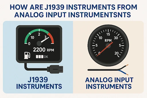
How are J1939 instruments different from analog input instruments
Types of Signal Inputs for Automotive Instruments
There are 3 types of signal inputs for the Automotive instruments (Gauges and clusters):
- Analog signal inputs or outputs
- CAN signal (J1939 signal)
- Mixed of Analog and CAN signal inputs & outputs
Analog Signal Inputs
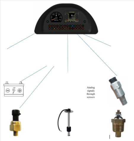
The Analog signals are based out of variable resistive, voltage, frequency, current and capacitive signals which mainly come through sensors. The instruments running at analog signals may not necessarily require the Electronics and software integration. The hardware of such instruments is generally complex to adapt all the signals in required range and hence the hardware cost becomes dependent on number and type of analog signals. The analog signals require the separate wire for each sensor signal to reach up to the instrument and due to signal distortion because of long wires and ambient or system noises, the signal input become noisy and create issues in the instrument. Therefore, good filtering in signal conditioning sections is required to remove such distortion and noises for better performance in harsh environments.
CAN Signal Inputs (J1939 Based)
The CAN signals (CAN2.0B or CAN-FD) are the digital signals based out of J1939 protocol system and mainly come through ECUs or sensors with ECU capability. The instruments running at CAN signals require the Electronics and software integration. The hardware of such instruments can be kept common for developing the any other instrument by just modification in software and applique design. The hardware of such instruments is generally simple, but the software is complex and require the proven stack for working flawlessly with other ECUs in vehicle. The CAN signal of up to 40 sensors (recommended in CAN standard for a certain length of wire) can be transmitted through two wires (recommended twisted pair cable) only and the signal is not affected through ambient and system noises. Hence it does not require the filters in hardware section.
Mixed Analog + CAN Signal Inputs
The mixed signals (Analog signals + CAN signal) is mix of both analog & CAN signal and this type of signals mainly come through sensors and ECUs jointly in vehicle system. The instruments running at this type of mixed signals require the Electronics and software integration. The hardware & software of such instruments is generally complex to adapt all the signals in required range and hence the hardware cost becomes dependent on number and type of required signals. The analog signals require the separate wire for each sensor signal to reach up to the instrument and due to signal distortion because of long wires and ambient or system noises, the signal input become noisy and create issues in the instrument. Therefore, good filtering in signal conditioning sections is required to remove such distortion and noises for better performance in harsh environments.
Configurable Signal Input Instruments
It is feasible to make the instruments with configurable signal inputs. This configurability can be achieved in two ways (a) through the hardware and (b) through the software.
The signal input configurability through hardware can be achieved by fitting the components at specified markings on the board as per the requirements. Example, if we fit the jumper or resistor at R1 then the instrument will recognize the resistive signal input and if we fit the jumper or resistor at R2 then the instrument will recognize the voltage signal input at the same pin of connector. This hardware configurability would be the permanent after delivery of product and can not be re-configured without opening the product.
Hence come the option of signal input configurability through software to overcome the problem of permanent fixing and it helps in reduction the variants of instruments required as per the engines. The software configurability can be achieved by developing the software in such a way that the instrument can provide the flexibility of selection of required signal input type for working to user. This selection of required signal input type can be configured by third party tools (based on the support of instrument), by inhouse developed tools worked on UART or CAN protocol or through the voltage inputs (like shorting of specified pins in connector externally). The method of software configurability is more popular and is evolved or finalized as per the understanding between OEM and supplier. Overall, the option of signal inputs configurability through software in the instrument saved a lot of inventory and costs of suppliers and OEMs in the present world seeing the number of engine options and vehicle models.
In today’s world, most of the OEMs use the instruments having signal input configurability through software and they use the customized tool which scans the bar code to read the engine parameters and configure the signal inputs of instrument accordingly. This process makes the interface between engine ECU & instrument flawless and foolproof within a very less time without hampering the production of vehicles in assembly line.
System Architecture for Analog signal-based instruments in vehicle
System Architecture for CAN signal-based instruments in vehicle
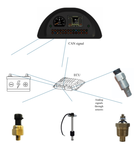
System Architecture for mixed signal-based instruments in vehicle