Powered by Smartsupp Blog Archives - Page 3 of 6 - Indication Instruments Ltd.
Problem-solving that actually sticks: practical techniques and why 8D works for us

Problem-solving that actually sticks: practical techniques and why 8D works for us

Why Electronic Pressure Sensors Are Superior to Electromechanical Pressure Sensors
Everyone face problems in their work or in daily real life. Problem solving depends on how we handle i.e. understand of actual problem and how we proceed for detailed analysis.
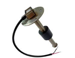
Patchwork fixes temporarily while Disciplined problem solving fixes causes. There are many problem solving techniques being used in automotive sector for products like digital instrument panel, instrument cluster digital, and electronic dashboard instruments like : PDCA, DMAIC, 5-Whys, Fishbone diagrams, FMEA and — the one we use extensively use— the 8D (Eight Disciplines) methodology.
Below we’ll walk through these techniques briefly and then review 8D in details i.e.how we use it day-to-day.

Brief details of problem-solving techniques

  • PDCA (Plan–Do–Check–Act) — This is iterative loop. Great for small experiments and continuous improvements.
  • DMAIC (Define–Measure–Analyze–Improve–Control) — This is backbone of Six Sigma. Use this when the problem needs statistical analysis and tight controls.
  • 5-Whys — Ask why regularly (at least 5 times) until you reach to actual root cause of problem.
  • Fishbone (Ishikawa) diagrams — This include all possible causes for problem including Man, Machine,Material, Method and Measurement. Great for team brainstorming and make sure you don’t miss important angles.
  • FMEA (Failure Modes & Effects Analysis) — a preventive, Potential risk-based technique to score risks and plan mitigations, typically used during design or process changes.

All of these techniques are useful. When an issue is cross-functional, impact customer, or requires both immediate containment and long-term fixes, the 8D method is often the most practical and reliable choice. This is especially true in complex assemblies such as electronic dashboard instruments and digital instrument panel systems.

What is 8D?

8D stands for Eight Disciplines. It’s a structured, team-based approach designed to solve complex problems and ensure they don’t recur.

  • D1 — Define the problem (4W/1H)
  • D2 — Form Team
  • D3 — Implement Interim Containment Actions
  • D4 — Root cause Analysis (5 why)
  • D5 — Select and implement Permanent Corrective Actions
  • D6 — Implement Preventive Actions
  • D7 — Confirm the effectiveness & Horizontal Deployment
  • D8 — Congratulate & Close

Two things make 8D powerful: early containment to protect customers and operations, and a disciplined progression from root-cause analysis through verified implementation and systemic prevention.

How we actually use 8D

D1: Define the problem (4W/1H)

A precise problem statement makes the investigation efficient. Replace vague descriptions like “For example, instead of saying ‘display not working,’ specify ‘backlight failure in instrument cluster digital during end-of-line testing” with specific statements: (Quote: “A problem is half solved if defined well.”)

What is actual problem?
Where is problem found?
When Problem Occurred?
Who reported problem?
How much Qty of failed part?

Define all aspects with relevant data evidence.

Note: Never ask ‘Why’ during define the problem.

Evaluate Severity of problem will help in prioritization.

D2: Form Team

8D is a CFT activity. A good 8D team includes all relevant cross function members like Process quality, Production, Supplier Quality, Engineering etc.Assign a clear team leader and capture member roles up front. That role clarity reduces confusion and speeds decisions during the investigation.

Why it matters? diverse perspectives catch blind spots, and having a named leader means actions get tracked and completed.

D3: Implement Interim Containment Actions

Containment buys you time to investigate. Actions include re inspection of stock available at customer site/Transit/ plant, quarantining suspect lots, stopping shipments, adding inspection steps. This is often required when issues occur in customer-critical parts like digital instrument panel or electronic dashboard instruments.

Record containment actions and results so you can later evaluate whether they were sufficient and when they can be withdrawn.

Doing GEMBA audit is also part of containment action.

D4: Root cause Analysis (5 why)

This is section where fishbone diagrams, 5-Whys start. Brainstorm systematically using Fishbone to cover all possible causes. Use 5-Whys to drill into the most likely branches.

In IIL we do root cause analysis for following area

  1. For occurrence
  2. For Non Detection
  3. System root cause

Main aspect of root cause analysis is that we need to validate the cause which determined by analysis i.e. ‘Root cause verification’

Root cause Verification can be done by physical witness of determined event or cause or by simulation of problem by determined cause.

It’s always a typical task to replicate the actual problem in same fashioned since multiple field factors are unknown.

Our prime focus is on root cause verification.
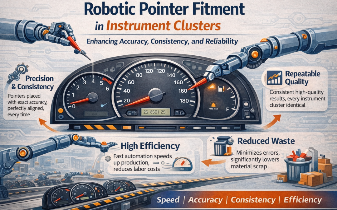
Related Blog : https://indicationinstruments.com/robotic-pointer-fitment-in-instrument-clusters/

D5: Select and implement Permanent Corrective Actions

Generate potential corrective actions for occurrence, non detection & system root cause fixing. Then validate them experimentally. A verified corrective action is demonstrated to fix the problem without introducing new issues. Define acceptance criteria and run controlled trials.

Note: Corrective actions should be in linkage with determined root cause.

D6: Implement Preventive Actions

During analysis we thoroughly study the process, part, design etc and take preventive action for potential risk/problem as a proactive approach.

Note: During implementation of permanent corrective actions/preventive actions. Update work instruction, control plan, FMEA etc. Assign responsibility and timelines for all action points with target date , track them for ontime implementation.

Verify the corrective actions status on regular interval to ensure all are in place.

D7: Confirm the effectiveness & Horizontal Deployment

Its always important to monitor the effectiveness of corrective action in future rejection returns trends/ quality concerns. This evident how much our corrective actions effective.

Deploy the actions horizontally where applicable in same family or similar design products.

D8: Congratulate & Close

Formally close the 8D after a period of monitoring and documented confirmation that targets were achieved.

Capture lessons learnt and celebrate the team.

Why Electronic Pressure Sensors Are Superior to Electromechanical Pressure Sensors

Why Electronic Pressure Sensors Are Superior to Electromechanical Pressure Sensors

Why Electronic Pressure Sensors Are Superior to Electromechanical Pressure Sensors

Pressure sensors work unnoticed in some of the most important applications surrounding us, including braking systems in vehicles, engine management, breathing aids in medicine, and manufacturing automation. Though there have been applications of electro-mechanical pressure sensors in earlier models, the preference in newer models is clearly in favour of electronic pressure sensors.

In this article, we’ll cover:

  • The evolution of pressure sensors
  • Electromechanical and electronic sensors: How do they work in reality?
  • How electronic pressure sensors outdo traditional methods of pressure measurement
  • Industries where this change is taking place
  • What IIL offers to meet market needs

Evolution of Pressure Sensors

1. Mechanical Pressure Measurement (The Starting Point)

Early pressure measurement relied entirely on mechanical movement:

  • Bourdon tubes
  • Bellows
  • Spring-loaded diaphragms

When force was applied to these elements, they distorted. These actions caused a needle to sweep across a dial. Such devices were simple, robust, and did not consume any power; they couldn’t transmit any electrical signal, remote monitoring, or data acquisition either.

Mechanical Pressure Measurement (The Starting Point)

Electromechanical Pressure Sensors (The Transition Phase)

Electromechanical sensors were an intermediary stage between mechanical and electronic designs.

They function in the following fashion:

  • Pressure pushes a mechanical diaphragm
  • A diaphgram will physically bent
  • This triggers a switch, potentiometer, or strain gauge
  • The mechanical process is translated into a fundamental electric signal

Key limitation: There is a friction due to mechanical motion.

Electromechanical Pressure Sensors (The Transition Phase)

3. Electronic Pressure Sensors (Modern Standard)

Electronic pressure sensors made it possible to eliminate any kind of dependence on mechanical elements to a large extent. Based on MEMS technology and semiconductor technology, they:

Electronic vs. Electromechanical Pressure Sensors

Accuracy & Precision

Electronic sensors provide the following functions:

  • High resolution
  • Excellent repeatability
  • Integrated temperature correction

In an electromechanical sensor, there is a mechanical movement that causes drift with respect to time

Reliability & Lifetime

Electromechanical sensors:

  • Wear out mechanically
  • Require frequent recalibration

Electronic sensors:

  • Free from mechanical fatigue
  • Long lasting performance

Response Time

These sensors respond almost instantly and are useful for:

  • Automotive braking
  • Industrial control loops
  • Medical life-support systems

Mechanical inertia slows electromechanical sensors.

Size & Integration

Thanks to MEMS:

  • Electronic sensors are compact
  • Easy to mount on PCBs
  • Ideal for IoT and embedded systems

Electromechanical circuits are larger and more difficult to miniaturize.

Connectivity & Intelligence

Electronic pressure sensors facilitate:

  • I²C, SPI, CAN, analog outputs
  • Diagnostics and fault detection
  • IoT compatibility

Electromechanical sensors do not have smart characteristics.

Total Cost of Ownership

Although electronic sensors would cost a bit more initially:

  • They last longer
  • Require less maintenance
  • Shorten downtime

Over time, they’re more economical.

Applications Propelling the Markets

  • Automotive: TPMS, engine controls, braking systems
  • Medical: Ventilators, patient monitoring, infusion pumps
  • Industrial: Hydraulics, pneumatics, process automation
  • Consumer electronics: HVAC, wearables
  • Aerospace: Altitude and cabin pressure monitoring

What IIL offers to meet market needs:

Electromechanical Pressure sensor:

  • It has pressure range up to 28 bar
  • With resistive output voltage
  • Available in different thread size for fitment
  • It is passive sensor so does not require power.
Electromechanical Pressure sensor

Electromechanical Pressure sensor

  • Is has pressure range up to 28 bar
  • Available in gauge and absolute pressure
  • Operating voltage: 5V (regulated), 5 to 32V for 12/24V vehicle
  • Output Voltage available in 0.5 to 4.5V and 0.5 to 4.9V
  • Different thread sizes are available for fitment.
  • Temperature compensated
  • Housing available in brass/ steel or free cutting steel material
Electronic Pressure Sensor

Conclusion

The shift from electromechanical to electronic pressure sensors is no longer a trend but an evolutionary process. The need for accuracy, speed, miniaturization, and digital intelligence in modern systems is effortlessly satisfied by electronic pressure sensors.

Frequently Asked Questions

Q1. What’s the biggest difference between electronic and electromechanical sensors?

Electronic sensors can translate pressure directly into an electrical signal, whereas electromechanical sensors must first use a mechanical motion.

Q2. Are electronic pressure sensors more accurate?

Yes — they provide increased accuracy, improved stability, and reduced drift.

Q3. Are electronic sensors calibrated?

Most of them are calibrated in the factory, although safety-critical applications may demand periodic recalibration.

Q4. Can electronic sensors withstand severe environments?

Absolutely. Absolutely. They have required specifications for withstanding high temperature, vibration, dust, and humidity.

Q5. Are electromechanical sensors in current usage?

Sometimes — in simplified or legacy systems, in cases when accuracy is not necessary.


What are different kinds of Platings used in Sensors and Why?

What are different kinds of Platings used in Sensors and Why?

What are different kinds of Platings used in Sensors and Why?

Electroplating is a process of depositing a layer of one metal on the surface of another metal by taking the help of electric current.

The part to be plated is made the cathode (negative electrode) and the material to be deposited is made the anode (positive electrode). There is an electrolyte which conducts electricity. When electric current passes through the system, positive metal ions flow from the anode and are deposited on the cathode

In zinc electroplating, zinc metal is used as an anode.

Plating is considered a special process, i.e. it is not possible to check for plating properties on the finished article without non destructive testing. Which means that to get a good plated parts, the plating conditions must be controlled very carefully.

Different Types of Electroplating

Zinc Plating

Zinc plating is an electroplating process in which a thin layer of zinc is deposited on the surface of steel components. It is cost-effective, easy to do, and provides corrosion resistance by two methods:

Zinc covers the steel and hence prevents exposure of the base metal to moisture and oxygen

Zinc is more electropositive than iron, which means it loses electrons more easily, and so it more reactive and provides sacrificial protection to iron / steel. This means that even if there is a small hole in the zinc coating, it will not let the exposed steel rust easily but will sacrifice itself first.

Passivation

Since zinc is highly reactive, it tends to get oxidized easily. Hence a passivation coating is done to protect the zinc itself from getting oxidised. Different passivation colours provide varying levels of salt spray life.

Also Read : https://indicationinstruments.com/robotic-pointer-fitment-in-instrument-clusters/

Types of Zinc Plating Based on Passivation

Trivalent Zinc Plating

Available in Blue / Clear, Yellow, Iridescent, and Black colours RoHS and REACH compliant

Hexavalent Zinc Plating

available in Yellow and Olive Green colours

Not acceptable under RoHS and REACH as it is hazardous to the environment and health

Limitations of Zinc Plating

It does not withstand high-temperature

There is a risk of hydrogen embrittlement in high-strength steels

Applications of Zinc Plating in Sensors

Zinc plating is extensively used in sensor components such as housings, brackets, Fasteners and covers

Key Steps in Zinc Electroplating

  • Cleaning: Remove all oils, dirt, rust, grease, and scale from the parts using alkaline cleaners, ultrasonic baths, or solvents. This is important as contaminants block adhesion of plating.
  • Rinsing: Thoroughly rinse parts cleaning
  • Acid Dipping: Dip in an acid bath (such as hydrochloric, sulfuric, or nitric acid) to activate the surface
  • Rinsing: Thoroughly rinse parts acid dip
  • Electroplating: Carry out the plating itself in a tank
  • Rinsing: Rinse thoroughly after plating.
  • Passivation / Chromating: Apply a chromate passivation coating
  • Sealing: A topcoat sealant can be added for better salt spray life
  • Drying: this can be done in a open atmosphere, an oven or even a conveyorized oven

Plating Solution

Composition: Contains zinc ions in the form of zinc oxide or sodium zincate. Additives such as brighteners, wetting agents, and pH buffers help in improve appearance and uniform thickness.

Additional Plating Types Used in Sensors

1. Zinc-Nickel Plating

Zinc-nickel plating usually contains 12–16% nickel and provides much better corrosion resistance compared to pure zinc. It provides uniform thickness even on complicated shapes and is preferred for safety and emission sensors. However, nickel is much more expensive than zinc and so the cost is higher than zinc plating.

2. Nickel Plating

Nickel plating is used where wear resistance, hardness, and conductivity are of importance. It is used in parts such as connector pins, shielding components, and signal contact surfaces. This is indeed very costly.

3. Electroless Nickel (EN) Plating

Electroless nickel is a chemical deposition process that does not involve electrical current at all. It provides uniform coating on complex shapes and has high hardness, wear resistance, and good corrosion protection. This is also quite expensive.

Related Read :https://indicationinstruments.com/how-shingo-model-improves-product-quality-automotive-sensors/

Frequently Asked Questions in Plating of Sensors

Q1. What are some of the common mistakes which occur in plating lines?

As stated earlier, plating is a special process, and requires good control of plating conditions. Some of the common mistakes are incorrect temperature control, inadequate agitation, improper current density settings, not using flowing water for rinsing, etc.

Q2. What is Hydrogen Embrittlement?

Hydrogen embrittlement is a failure mode in which high-strength steels become brittle and crack. This happens due to the absorption of hydrogen atoms during zinc plating processes.

During electroplating, hydrogen is generated at the cathode and hydrogen atoms can diffuse into the steel part. This can result in a reduction in ductility and toughness, which in turn may result in cracking. Often such cracking is delayed.

Hydrogen embrittlement often affects high-strength steels, especially carbon steel and alloy steel.

Hydrogen embrittlement can be avoided by minimizing acid exposure time, using inhibitors in acid baths, and maintaining the current density during plating.


Why Capacitive Fuel Level Sensors Preferred over Reed-Switch For Tracking of Fuel Theft

Why Capacitive Fuel Level Sensors Preferred over Reed-Switch For Tracking of Fuel Theft

Robotic Pointer Fitment in Instrument Clusters<br />

Fuel theft has become a widespread challenge today, affecting fleets, trucks, generators, mining operations, and heavy equipment users alike. With diesel prices rising every year, it’s an issue no one can afford to ignore anymore.

For a long time, reed-switch fuel level sensors were the standard option. They did the job “well enough,” but technology has moved on. Capacitive fuel level sensors have basically taken over with better accuracy, resolution and reliability.

1. How Capacitive Sensors Improved Over the Years

Capacitive sensors weren’t even meant for vehicles originally. They started in industrial tanks where precision mattered more than cost. Slowly, as telematics entered the automotive world, this tech made its way into trucks and heavy equipment.

At first, these sensors were quite simple with metal tubes, analog output, and a lot of manual calibration. Over time, companies began developing smarter versions with digital electronics, better stability, and the ability to program sensor length.

The latest generation is far more advanced. You’ll find:

  • Dual-probe systems that adjust themselves
  • Temperature-based correction
  • Proper RS485 or CAN output
  • Better filtering against vibration and electrical noise

This is the point where capacitive sensors really pulled ahead of reed switches.

2. Capacitive vs. Reed-Switch Sensors: What Actually Happens Inside

Capacitive Sensors

Capacitive Sensors
The fuel becomes part of the measurement system. As it rises or falls, it changes the capacitance between two probes. The electronics inside convert this into a continuous reading.

Reed-Switch Sensors

Reed-Switch Sensors
These use a float with a magnet inside the tank. As it moves up or down, it triggers different magnetic switches. The reading jumps in steps rather than gradually. That “stepping” is one of the biggest drawbacks.

Why Capacitive Sensors Usually Win

1. They’re More Accurate

Capacitive sensors give smooth readings. Small changes show up immediately. Whereas Reed switches jump after every few millimeters. Imagine trying to track theft of 1-2 litres with a sensor that only updates after 10-20 litres depending upon tank capacity.

2. No Moving Parts

Anything with a float or magnet is eventually going to stick, jam, or wear out. Capacitive probes are solid-state. Nothing moves, nothing rubs, nothing gets stuck.

3. Better at Catching Theft

Because capacitive sensors pick up small changes, they detect:

  • Quick siphoning
  • Partial theft
  • Tampering
  • Even odd refilling behaviour

Reed switches simply can’t capture these micro-changes.

4. They Handle Vibration Better

On a mine truck or even an old diesel generator, vibration is part of life.
Floats bounce around in these conditions — which means wrong readings.
Capacitive probes stay stable.

5. They Last Longer

A good capacitive sensor can run for more than 10 years without much trouble.

6. Easy to Connect to Modern Telematics

Most GPS and telematics platforms just plug into RS485 or CAN.

A Few Downsides

  • Capacitive sensors do cost more.
  • They also need proper calibration.
  • Different fuels (diesel, biodiesel, kerosene mix) can affect readings — unless the sensor compensates for it.

3. What Indication Instruments Has Done Differently

IIL has actually improved capacitive technology in a way that solves some of the usual issues.

Dual-Probe Compensation

Fuel mixtures can change from pump to pump. Biodiesel content especially varies a lot.
IIL uses two probes to automatically adjust for these changes. This helps maintain accuracy without constant recalibration.

Built-In Temperature Compensation

Fuel expands when hot and contracts when cold.
Using temperature correction keeps readings accurate throughout the day and even in places where the temperature shifts drastically.

Stronger, Industrial Build

Things like:

  • IP67 / IP69K protection
  • Anti-corrosion materials
  • Vibration-proof design

make them more reliable in rough environments.

Works With Any Telematics Setup

Whether your system uses CAN or 0.5 –5V integration is straightforward.

Compatible With Different Fuels

Diesel, biodiesel, and ethanol blends all work fine.

Also Read : Mechanical Temperature Gauge Benefits & Why It’s Still a Popular Choice around peoples

4. Extras That Make Capacitive Sensors More Practical

Zero Maintenance

Since there are no moving parts, there’s almost nothing to service.

Better Theft Alerts

A proper capacitive sensor can show sudden drops, unusual refills, and night-time siphoning clearly on a graph.

Real Cost Savings

Fleets that switch over usually report noticeable drops in theft within a few weeks.

Better Data for Analysis

When combined with telematics, operators can track:

  • Driver habits
  • Route-wise fuel consumption
  • Fuel efficiency patterns

Conclusion

When you compare both technologies in real-world usage, capacitive sensors clearly come out ahead, especially when theft detection and accuracy matter. With added features like dual-probe compensation and temperature correction, modern capacitive sensors have become the go-to choice for serious fuel monitoring.

Indication Instruments has helped push this shift by building durable, reliable, telematics-friendly capacitive sensors designed specifically for tough fleet and industrial environments.

FAQs

1. Why are capacitive sensors better for theft detection?

They read continuously and can detect even tiny changes in fuel level.

2. Does temperature affect readings?

Normally yes — but IIL sensors compensate automatically.

3. Can they work with mixed fuels?

Yes, especially with the dual-probe design.

4. How long do they last?

Usually more than 10 years.

5. Are they easy to install?

Yes, they can be cut to size and calibrated easily.

6. Will they work with my GPS tracker?

Most likely yes.


Robotic Pointer Fitment in Instrument Clusters

Robotic Pointer Fitment in Instrument Clusters

Robotic Pointer Fitment in Instrument Clusters<br />
When we sit in a car, the instrument cluster is the first thing we notice. Speed, RPM, fuel, temperature, warning lights, everything the driver needs is shown there. If this information is not accurate, the driver immediately feels something is wrong. Even a small mismatch in pointer position creates doubt about the vehicle.
That’s why the quality of an instrument cluster matters so much.
One small step in this assembly is pointer fitment. It looks simple, but in reality, it is one of the most sensitive operations in the entire cluster build. A small mistake at this stage can easily pass unnoticed and later turn into a customer complaint or warranty issue.
For many years, pointer fitment has been done by hand. Operators press the pointer onto the motor shaft using fixtures or simple tools. This worked when volumes were low and expectations were moderate. But today, with higher volumes, tighter tolerances, and zero-defect expectations, manual fitment has become risky. This is where robotic pointer fitment comes into the picture.

What exactly is pointer fitment?

Pointers are the needles seen on the speedometer, tachometer, fuel gauge, and temperature gauge. These pointers are pressed onto very small stepper motor shafts.

This pressing has to be done very carefully:

  • The pointer must sit exactly at zero
  • The height must be correct and uniform
  • The force must be just right—not too much, not too little
  • The motor gears must not get stressed
  • The pointer and dial must remain scratch-free

If anything goes wrong, the pointer may stick, give wrong readings, or look visually misaligned. Many times, the cluster looks fine after assembly, but issues appear only during functional testing or later in vehicle usage.

Why manual fitment causes problems

Even skilled operators face limitations with manual pointer fitment.
First, no human presses the same way every time. One press may be slightly harder, another slightly softer. Fatigue, long shifts, and pressure to meet targets all affect consistency.
Second, issues are detected late. Most pointer-related problems show up only during end-of-line testing. By then, rework is difficult, and sometimes the entire cluster has to be rejected and scrapped.
Third, there is always a risk of hidden damage. Excess force can damage the motor internally. Less force can cause the pointer to become loose later, especially during vehicle vibrations resulting in the pointer coming out of the stepper motor.
Another big challenge is no process data. Manual fitment gives no information about force or depth. When problems occur in the field, finding the real cause becomes difficult.
Finally, pointer fitment is physically and mentally tiring. It requires focus, steady hands, and repetition. Over time, this affects quality and operator well-being.

Also Read : Analog vs Digital Instrument Cluster: Key Differences Explained

How robots make a difference

A robot does not get tired. It does not rush. It does not change its method between shifts.
With robotic pointer fitment, the process becomes stable:

  • The pointer is aligned the same way every time
  • Pressing force stays within limits
  • Height and clearance remain consistent
  • Motor damage is avoided
  • Data of pointer height and force can be stored corresponding to cluster serial number.

Once the parameters are set and validated, the robot simply repeats the process perfectly, day after day.

What happens inside a robotic cell

The process is straightforward.
The cluster is placed in a fixed fixture with clamping to ensure correct positioning.
The robot carefully picks the pointer using soft grippers or vacuum cups so that the pointers do not get scratched or damaged.
The stepper motor is electrically moved to its zero position.
The robot then presses the pointer using a controlled press while monitoring force and movement.
If anything goes outside limits, the part is rejected immediately.
All this information is stored for traceability.

Real benefits on the shop floor

Plants that have moved to robotic pointer fitment usually notice improvements very quickly:

  • Fewer alignment complaints
  • Better consistency across shifts
  • Higher first-pass yield
  • Reduced rework and scrap

Supervisors also find it easier to control quality because the process is defined and measurable.

Is it worth the investment?

At first glance, robotics looks costly. But over time, the benefits add up.
Rework reduces. Scrap reduces. Warranty risk reduces. Production becomes more predictable. Dependence on individual skill reduces.
Over the full life of the program, robotic pointer fitment often turns out to be more economical than manual methods.

Final thoughts

Pointer fitment may look like a small job, but it has a big impact on customer trust. Manual fitment depends heavily on human skill, which naturally varies. Robotic fitment depends on a controlled process, which stays consistent.
Robotic pointer fitment is not about replacing people. It is about protecting quality and removing variation.
A small needle, fitted correctly, makes the entire instrument cluster reliable.

Frequently Asked Questions

1. Why is robotic pointer fitment more reliable than manual pointer fitment?

Robotic pointer fitment ensures the same pressing force, accurate pointer height, and perfect zero alignment every time. Unlike manual fitment, with skill differences between operators, their fatigue, or technique affecting quality, a robotic system will always maintain controlled parameters. This eliminates hidden damage to stepper motors and significantly reduces alignment-related customer complaints.

2. Whether pointer-related defects in instrument clusters can be eliminated totally by using robots.

Robots drastically reduce defects, but no industrial process is 100% defect-free. However, robotic pointer fitment eliminates major sources of variation such as over-pressing, under-pressing, angular misalignment, and dial scratches. Because the robot stores force and height data for every cluster (traceability), issues can be diagnosed quickly, making overall defect rates extremely low compared to manual processes.

3. Is robotic pointer fitment suitable for all types of instrument clusters, including EV clusters?

Yes. Whether the cluster is analog, hybrid, or EV-based, the fitment requirement of the pointer remains the same: precisely aligned, controlled in force, and correct in height. Robots can be programmed for various cluster models, pointers, and types of stepper motors. In EV instrument clusters, where customer expectations on accuracy and aesthetics are even higher, robotic fitment ensures consistency in quality and supports zero-defect manufacturing goals.


Benefits of 5S in the Workplace for Better Work Culture

Benefits of 5S in the Workplace for Better Work Culture

j1939-instruments-vs-analog-input-instruments
5S is a workplace organization method using five Japanese words starting with “S” to improve efficiency, safety, and productivity. Hence, it is widely adopted in the manufacturing units for instrument clusters, automotive instrument clusters, and other precision automotive components.

5S is very important in ensuring quality, safety, and efficiency in automotive instrument cluster, dashboard speedometer, and EV instrument cluster production companies in India, which are major players in the automotive parts industry.

Sort (Seiri)

Get rid of all unwanted items at the workplace. Categorize into 3 groups-“scrapped”, “can be used by other departments”, “can be used in future”.

Set in Order – Seiton

A place for everything and everything in its place. No unidentified object in the zone should be there.

Shine (Seiso)

Clean the workplace and keep it clean. Rust, dust, broken, faded paint should not be seen in the department.

Standardize (Seiketsu)

Develop procedures, guidelines, schedules, and checklists that will help maintain the first three S’s, which are Sort, Set in Order, and Shine.

Sustain (Shitsuke)

Develop discipline and habits to follow the established standards, conduct regular audits. Encourage everyone to maintain the 5S, train them, and allow display before-after stories.

How to Implement 5S in a Factory?

Divide the Factory into Zones

Divide the entire factory area into different zones, assigning one zone leader to each zone and making them responsible for all activities related to 5S within their area.

Involve All Team Members

Ask every zone leader to engage each team member within the zone with the 5S activities. Properly train everybody on 5S in order for them to understand the principles and benefits of 5S.

Shoot “Before” Photographs, Documenting Progress

Start by taking “before” pictures of each area. Create a tracking sheet to which these photos are attached. Identify gaps, work on closing them, and then update the sheet with “after” photos so improvements are clearly visible.

Implement 5S Step-by-Step

Start with 1S (Sort) and progress through 2S (Set in Order), 3S (Shine), and so on, up to the full 5S sequence.

Develop Zone-Specific Procedures

Each zone leader should prepare a written procedure for their zone. This should include:

  • 5S activity timings: daily, weekly, etc.
  • Cleaning schedule for 1S red-tag area
  • Responsibilities of sub zone leaders and each member
  • 5S trainings
  • Any other points that is important or related to 5S can be written in this

The zone leader should be encouraging and motivating everybody consistently to follow the procedure and understand the benefits of 5S.

During 5S, also focus on Safety: raise discrepancy in Safety incident report format where you find the safety issue.

Establish a common space for reusable materials

Set up a common area where items that are still useful can be placed so others can reuse them if needed.

Prepare an Audit Plan and conduct audit

Develop an audit plan along with a list of auditors. Regularly perform 5S audits, provide feedback, and request improvement where necessary.

Also Read : How Indication Instruments Improve Safety

Benefits of 5S in factory

Space saving

One of the first things you notice with 5S is the sudden increase in space.
You instantly see good floor and storage space by sorting out unwanted materials and organizing the workplace.

Increase productivity

When everything has a place and everything is in its place, then work becomes smoother and faster. Teams do not waste their time rummaging for tools or documents.
Productivity increases because people can focus on their tasks, instead of wasting time in order to find materials, tools, or documents in surroundings.

Improve quality

A clean and organized workplace reduces issues automatically.
It is easier to detect problems earlier, follow procedures correctly, and maintain quality consistently.

Time saving

A lot of time is just wasted looking for things.
With 5S, that time saves
Tools, materials, and documents are placed at their location and clearly labelled, so that finding them will be easy and save time. The time saved will be utilised in more production.

Company beautification

A well-organized workplace gives pride to the employees as well as confidence to the visitors.
Clean floors, organized racks, pallets, storage area; cleared marking gangways/walkways of every assembly line, fans, and lights in symmetry. A healthy environment makes the company look good and disciplined.

Attract new customers

Every customer wants that the organisation they are visiting should be well organised, clean and everything systematic-all these things send positive feedback of a companies’ environment.

Reduce accidents, improved safety, and machine life.

5S reduces workplace accidents because, while doing 5S, any unsafe condition observed raises a Safety Incident Report, or machines and tools requiring repair or any leakage found is sent to maintenance, which reduces accidents and improves the life of machines and tools. Clear pathways, labeled zones, properly stored tools, and mean very less chance of hazards. A safe workplace gives confidence to the employees.

Positive zone environment

5S improves bonding within the zones; as it involves everyone in 5S related activity, it creates a positive environment, works together, everyone takes ownership, and improves the zone.

Low cost

5S helps in reducing the 7 kinds of waste and non-value-added jobs that save cost and improve efficiency.

FAQs:

Can 5S improve employee morale?

Yes, 5S can boost morale by creating a cleaner, safer, and more organized work environment, reducing stress, and increasing pride in the workplace

How does 5S impact quality in manufacturing?

5S improves quality by ensuring that only the necessary tools and materials are used, minimizing the chance of errors due to clutter or disorganization.