")
Introduction: When the Dashboard Became a Network Node
Years ago, when I first worked with embedded display systems for automotive applications, the instrument cluster was treated as a relatively peripheral component. It showed the driver what they needed to see, speed, fuel level, temperature, RPM, and that was essentially the full extent of its job. There was no architecture discussion, no integration planning, no protocol matrix. You wired it up, calibrated the gauges, and moved on to the next thing.
That world no longer exists. And if I am honest, I think a significant portion of the industry is still catching up to just how much the role of the instrument cluster has changed.
Today, the modern instrument cluster sits at the intersection of sensor networks, embedded processing, cloud platforms, and telematics infrastructure. It is not simply a display. It is an active network node, processing data from dozens of vehicle systems in real time while simultaneously participating in a continuous two-way flow of information that extends well beyond the vehicle itself.
The global connected car market is projected to exceed USD 166 billion by 2025, according to Allied Market Research. The broader vehicle telematics segment is expected to reach USD 107 billion by 2028. These are not incremental numbers. They represent a structural shift in how vehicles are designed, operated, and managed at scale.
This post walks through the actual architecture of instrument cluster and telematics integration, the communication protocols that make it function, the measurable business outcomes it drives in fleet operations, and where the technology is headed over the next few years.
What Modern Instrument Clusters Actually Do
The first thing I tell engineers new to this problem space is this: a connected instrument cluster is not a passive screen. It is an active ECU (Electronic Control Unit) node. That distinction matters a great deal when you start designing telematics integration.
At the hardware level, a connected cluster runs on an automotive grade system on chip, processing inputs from the vehicle’s CAN bus network, applying rendering logic, and outputting to a high resolution TFT or OLED display. The SoC also handles communication with the telematics control unit, manages ADAS overlay data, and in more advanced implementations supports bidirectional communication with remote fleet management platforms.
The market reflects this functional expansion. The global digital instrument cluster market is projected to reach USD 10.9 billion by 2028, according to Markets and Markets, growing at a CAGR of 6.8 percent from 2023. That growth is not primarily about aesthetics, though the visual transformation has been dramatic. It is driven by the functional requirements that connected vehicle programs impose on cluster hardware and software.
In practical terms, three shifts define the modern cluster’s expanded role. First, clusters now receive and process ADAS data in real time, rendering lane departure alerts, forward collision warnings, and blind spot indicators directly on the primary display. Second, they act as HMI hubs that bridge the driver and the vehicle’s underlying ECU network, surfacing information from dozens of subsystems through a single, coherent interface. Third, and most relevant for telematics integration, they function as data gateway interfaces that actively exchange information with the telematics control unit (TCU) mounted elsewhere in the vehicle.
I have seen deployments where engineering teams treated the instrument cluster as an output-only device well into the architecture phase, then struggled to retrofit bidirectional capability. The time to plan for telematics integration is at the hardware selection stage, not after. When reviewing digital display and cluster solutions for any connected vehicle program, protocol support and communication architecture should be the first evaluation criteria on the list, not the last.
Telematics Integration Architecture: How the Layers Fit Together
Telematics integration in a connected vehicle follows a layered architecture. Understanding each layer is essential before committing to hardware or software choices.
The Vehicle Layer: CAN Bus and Beyond
The CAN (Controller Area Network) bus remains the primary communication backbone for in-vehicle networking. Developed by Bosch in the 1980s, CAN allows multiple ECUs to communicate over a shared bus without a host computer, with data frames transmitted at speeds of up to 1 Mbit/s on high speed networks. Most modern vehicles run multiple CAN segments: a high speed network for powertrain and chassis systems and a lower speed network for body electronics.
The instrument cluster reads from this bus continuously. Messages from the engine control module, transmission, braking systems, and chassis sensors arrive as structured CAN frames that the cluster decodes and renders visually. The cluster itself also generates messages, broadcasting display status and user input events back onto the bus.
The Telematics Layer: TCU and Data Transmission
The telematics control unit sits on the same CAN bus and reads the same message traffic. It applies filtering logic to extract relevant parameters, aggregates them into structured packets, and transmits them over a cellular connection (typically LTE Category 1 or Category 4) to the fleet management backend. In basic architectures, this is one directional. The vehicle sends data. Nothing comes back to the cluster display.
In advanced implementations, the TCU and cluster share a dedicated communication channel. The fleet management platform can push driver performance data, routing updates, or operational alerts back through the TCU to the cluster display. This bidirectional model is more complex to implement but dramatically expands what telematics actually delivers to operators.
The Cloud Layer: Platform and Analytics
The cloud backend receives data streams from connected vehicles, applies analytics and machine learning models, and surfaces insights through a fleet management dashboard. Predictive maintenance alerts triggered by anomalous sensor patterns, fuel efficiency benchmarks comparing driver behavior across the fleet, and compliance reports for regulatory requirements all originate at this layer before being pushed back through the TCU to the cluster display.
According to McKinsey, the shift to over the air (OTA) updates enabled by this architecture is expected to reduce vehicle service costs by up to 35 percent over the vehicle lifetime. For fleet operators managing hundreds of vehicles, the compound efficiency is substantial. The instrumentation solutions at Indication Instruments are specifically engineered for the high reliability, real time communication demands that this kind of connected vehicle architecture requires.
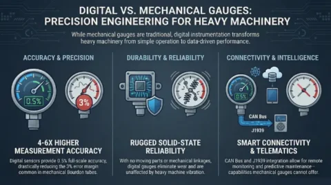
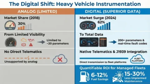
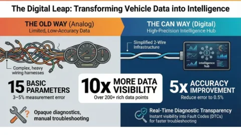
Traditional vs. Connected Instrument Clusters: A Feature Comparison
The table below summarizes the key functional differences between a traditional instrument cluster and a connected cluster with full telematics integration. These distinctions directly affect procurement decisions, integration complexity, and the operational value delivered across a fleet program.
| Feature | Traditional Instrument Cluster | Connected Cluster with Telematics |
|---|---|---|
| Data Communication | One-way local display only. No outbound data path. | Bidirectional communication with TCU and cloud fleet platform. |
| Protocol Support | Analog sensor inputs or basic CAN reading. | CAN, LIN, Ethernet, OBD-II, J1939 depending on vehicle class. |
| Remote Diagnostics | Not available. Manual inspection required. | Real time fault code transmission to fleet management backend. |
| Over the Air Updates | No OTA capability. Physical servicing required. | Firmware and configuration updates pushed over cellular channel. |
| Driver Performance Feedback | Static gauges only. No scored metrics displayed. | Live performance scoring calculated from cloud analytics and rendered on cluster. |
| ADAS Integration | Limited or none. No sensor fusion overlay. | Full sensor fusion overlays including lane alerts, collision warnings, and blind spot indicators. |
| Fleet Visibility | Zero. No remote visibility for fleet operators. | Live GPS position, speed, health status, and driver behavior per vehicle. |
| Data Latency | Not applicable. No external data path. | CAN read under 100ms. Cloud push latency typically under 2 seconds. |
| Predictive Maintenance | Odometer or time based service intervals only. | Sensor driven alerts surfaced on cluster display from predictive backend models. |
| Cybersecurity Requirements | Not applicable. Isolated system. | Secure boot, firmware signing, encrypted communication, and access controls required. |
Communication Protocols: What Powers the Connection
The protocol layer is where most telematics integration projects encounter real complexity. I have seen programs that looked straightforward on paper stall for months because the protocol compatibility between the cluster hardware, the TCU, and the cloud backend was not properly specified from the start.
CAN and OBD-II: The Universal Foundation
CAN is the foundational in-vehicle protocol. Its deterministic behavior and fault-tolerant design make it well suited for real time sensor communication in safety-critical systems. OBD-II provides a standardized diagnostic interface layer on top of CAN, enabling external devices to query vehicle parameters using standard PIDs (Parameter IDs). Standardized in the United States since 1996, OBD-II is the connection point for the vast majority of aftermarket telematics devices in passenger and light commercial vehicle deployments.
SAE J1939: The Commercial Fleet Standard
SAE J1939 extends CAN for commercial and heavy duty vehicle applications using a more sophisticated parameter group numbering (PGN) system. It supports granular tracking of metrics specific to trucking, construction, and transit applications, including engine torque, exhaust temperature, axle load distribution, and hundreds of other parameters not available through standard OBD-II. For any deployment involving commercial fleets, J1939 fluency is absolutely essential. It is not optional.
LIN, MOST, and Automotive Ethernet
LIN (Local Interconnect Network) handles lower bandwidth peripheral tasks within the vehicle, such as seat position sensors and mirror controls. MOST (Media Oriented Systems Transport) is used in premium vehicles for high bandwidth multimedia data. Automotive Ethernet, specifically the 100BASE-T1 and 1000BASE-T1 standards, is rapidly becoming the protocol of choice for high bandwidth applications including camera feeds, ADAS sensor data, and over the air update channels where CAN’s throughput limits become a constraint.
When evaluating instrument cluster options for telematics-intensive applications, the two questions I always ask first are: which protocols does this hardware natively support, and what is the latency profile under peak CAN bus load? The answers to those two questions alone will eliminate a significant portion of options that appear attractive on a datasheet but fail in real integration conditions.
Fleet Telematics: Where Connected Instrument Clusters Deliver the Most Value
The commercial vehicle sector has pushed connected instrument cluster technology further than any other segment, and the reasons are straightforward. Fleet operators managing hundreds or thousands of vehicles need operational visibility that extends far beyond what any individual driver can communicate manually. The instrument cluster is the most direct interface between the fleet’s telematics infrastructure and the human operator.
In a typical fleet telematics deployment, the instrument cluster displays not just speed and fuel level but a live driver performance score updated every few minutes based on hard braking events, idling duration, and posted speed compliance. This data flows from the cluster through the TCU to the fleet management platform, where dispatchers see aggregate metrics across the entire fleet in a browser-based dashboard.
The financial case for this integration is well documented. McKinsey research indicates that connected fleet telematics reduces fuel costs by up to 15 percent and improves vehicle uptime by approximately 30 percent through predictive maintenance capabilities. At fleet scale, those percentages translate into material cost reductions and significant improvements in service reliability.
There are also less quantified but equally real benefits in driver safety. When the instrument cluster surfaces real time coaching data directly to the driver rather than passing it through a management review cycle, behavior change happens faster. Drivers respond to feedback they can see on the screen in front of them during the drive, not to a weekly email summary reviewed after the fact.
For industrial and fleet applications where display reliability under demanding conditions matters as much as connectivity capability, the digital display and panel meter range at Indication Instruments provides options specifically rated for the temperature ranges, vibration environments, and ingress protection requirements that commercial vehicle deployments impose.
Where This Technology Is Headed: Three Trends Worth Watching
I am cautious about making bold predictions in a space that moves as quickly as connected vehicle technology. But three trends are visible enough in current programs that I think they are worth examining clearly.
V2X Communication Entering Production
Vehicle to Everything (V2X) communication is transitioning from research programs into production vehicle deployments. V2X enables vehicles to communicate not just with backend cloud platforms but with other vehicles and road infrastructure in real time. For the instrument cluster, this means becoming a display interface for infrastructure data: traffic signal phase timing, road hazard alerts issued by vehicles ahead, and emergency vehicle preemption notifications. The latency requirements for safety-critical V2X applications sit under 20 milliseconds round trip. That demands careful optimization across the entire data path from sensor input to cluster rendering.
AI Driven Display Personalization
Machine learning models trained on driver behavior data are enabling adaptive cluster layouts that shift in real time based on context. The display adjusts information density based on detected fatigue indicators, reconfigures alert thresholds based on road and weather conditions, and prioritizes the data most relevant to the cargo type or route. Several Tier 1 suppliers have production-ready implementations in 2025 programs. Broad adoption at scale across commercial fleets is probably two to three years away, but it is coming.
Over the Air Updates as a Baseline Requirement
Over the air update capability is moving from a premium feature to a baseline procurement requirement in new vehicle programs. Getting OTA right across a distributed fleet requires a well-architected backend, robust delta update packaging, secure rollback capability at the firmware level, and a thorough testing regime that validates updates across the full hardware variance of the fleet. The engineering complexity of doing this safely at scale is real and should be treated as a system design problem from the start. The operational and cost benefits make it worth the investment.
If you are at the specification stage for a connected vehicle program and want to talk through what display and instrumentation architecture makes sense for your specific requirements, the team at Indication Instruments has the application experience to provide useful guidance.
Frequently Asked Questions
Q1: What makes an instrument cluster “connected” as opposed to a traditional one?
A connected instrument cluster has the capability to communicate with onboard telematics systems, receive inbound data from cloud platforms, and in advanced implementations transmit its own operational status to a remote management interface. A traditional cluster reads from sensors and displays data locally with no external communication path. The distinction becomes significant the moment you need fleet visibility, remote diagnostics, or driver performance feedback.
Q2: How does the instrument cluster interact with the telematics control unit?
The cluster and TCU share the same CAN bus in most vehicle architectures. The TCU reads CAN messages generated by the cluster and other ECUs, processes them, and transmits aggregated data to the cloud backend over a cellular connection. In bidirectional architectures, the TCU can push incoming cloud data back onto the CAN bus as structured messages that the cluster reads and renders. This two-way model enables real time driver coaching, remote alerting, and OTA configuration updates visible on the cluster display.
Q3: What is the significance of SAE J1939 for commercial fleet telematics?
SAE J1939 provides a parameter set specifically designed for heavy duty and commercial vehicle applications. It supports granular tracking of metrics including engine torque, exhaust temperature, axle weight distribution, and hundreds of parameters not available through standard OBD-II. For fleet operators in trucking, transit, or construction equipment management, J1939 compatibility in both the instrument cluster and the TCU is a baseline requirement, not an optional upgrade.
Q4: Can aftermarket telematics devices fully replace OEM telematics integration?
Aftermarket OBD-II telematics devices read vehicle data effectively and are widely deployed in fleet programs. However, they typically do not support bidirectional communication with the instrument cluster display, which limits their ability to surface performance data or alerts directly to the driver through the cluster. Fully integrated OEM solutions offer more complete capability at the cost of greater hardware complexity and typically higher procurement cost. The right choice depends on whether driver-facing feedback through the cluster is a requirement for your program.
Q5: What cybersecurity considerations apply to connected instrument cluster deployments?
Security is increasingly central to connected vehicle architecture. The CAN bus in most vehicles has limited native security, making perimeter security at the TCU level and proper network segmentation critical design requirements. Over the air update channels require signed firmware packages, secure boot processes, and intrusion detection capability at the vehicle level. As vehicle systems become more networked, the attack surface expands meaningfully. Security architecture needs to be embedded from the specification stage, not added as an afterthought when a vulnerability is discovered.
Q6: Where can I find instrument cluster and digital display solutions suited to telematics-integrated deployments?
Indication Instruments offers a product range covering digital displays, panel meters, and instrumentation systems designed for high-reliability and connectivity-capable deployments across automotive, industrial, and commercial vehicle applications. Explore the full product catalog or contact the team directly for application-specific guidance.
Related Articles
- Understanding CAN Bus Architecture in Modern Vehicle Electronics
- OBD-II vs. SAE J1939: Choosing the Right Protocol for Your Fleet Telematics Program
- Digital Display Selection Guide for Industrial and Automotive Applications
- How Fleet Operators Are Using Predictive Maintenance to Cut Downtime by 30 Percent
- V2X Technology: What Connected Vehicle Programs Need to Know in 2025 and 2026

Chief Technology Officer, Indication Instruments Ltd.
Anuj Garg has led the engineering and product development function at Indication Instruments for more than 2 decades, overseeing the design and manufacture of instrument clusters, sensors, and driver information systems for ICE and EV platforms across two-wheeler, commercial vehicle, and off-road segments. He has hands-on experience with cluster architecture for BS6 commercial vehicles, electric 3-wheelers, fleet applications, heavy vehicles, farm equipments, and leads the company’s technology roadmap.
LinkedIn: Anuj Garg