Powered by Smartsupp Indication Instruments, Author at Indication Instruments Ltd. - Page 3 of 5
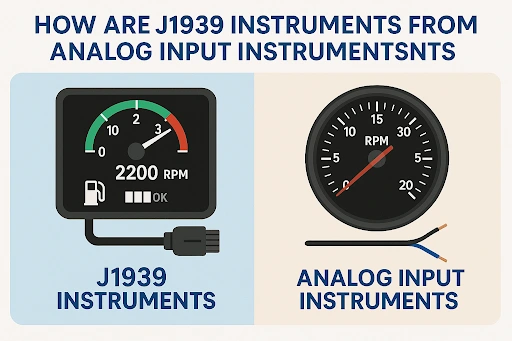
How are J1939 instruments different from analog input instruments

How are J1939 instruments different from analog input instruments

j1939-instruments-vs-analog-input-instruments

Types of Signal Inputs for Automotive Instruments

There are 3 types of signal inputs for the Automotive instruments (Gauges and clusters):

  1. Analog signal inputs or outputs
  2. CAN signal (J1939 signal)
  3. Mixed of Analog and CAN signal inputs & outputs

Analog Signal Inputs

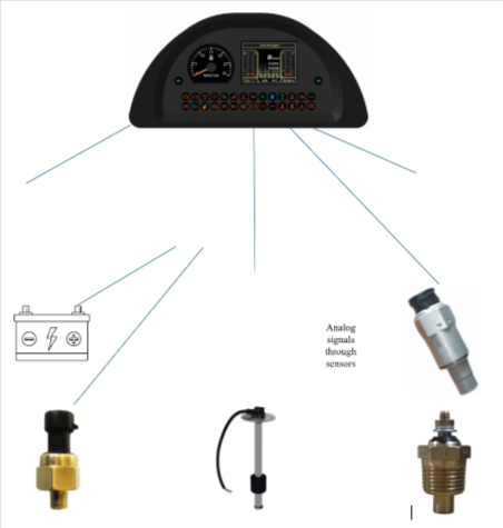
The Analog signals are based out of variable resistive, voltage, frequency, current and capacitive signals which mainly come through sensors. The instruments running at analog signals may not necessarily require the Electronics and software integration. The hardware of such instruments is generally complex to adapt all the signals in required range and hence the hardware cost becomes dependent on number and type of analog signals. The analog signals require the separate wire for each sensor signal to reach up to the instrument and due to signal distortion because of long wires and ambient or system noises, the signal input become noisy and create issues in the instrument. Therefore, good filtering in signal conditioning sections is required to remove such distortion and noises for better performance in harsh environments.

CAN Signal Inputs (J1939 Based)

The CAN signals (CAN2.0B or CAN-FD) are the digital signals based out of J1939 protocol system and mainly come through ECUs or sensors with ECU capability. The instruments running at CAN signals require the Electronics and software integration. The hardware of such instruments can be kept common for developing the any other instrument by just modification in software and applique design. The hardware of such instruments is generally simple, but the software is complex and require the proven stack for working flawlessly with other ECUs in vehicle. The CAN signal of up to 40 sensors (recommended in CAN standard for a certain length of wire) can be transmitted through two wires (recommended twisted pair cable) only and the signal is not affected through ambient and system noises. Hence it does not require the filters in hardware section.

Mixed Analog + CAN Signal Inputs

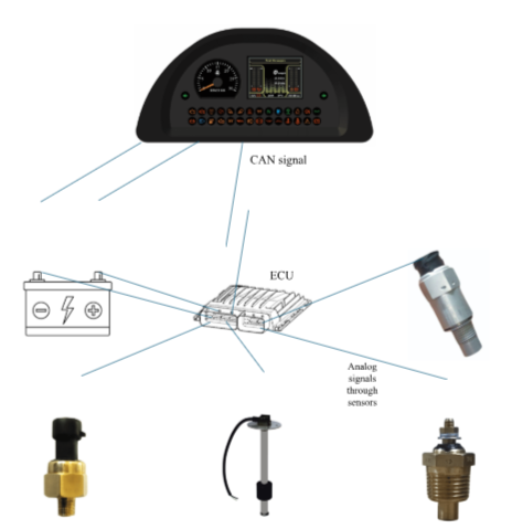
The mixed signals (Analog signals + CAN signal) is mix of both analog & CAN signal and this type of signals mainly come through sensors and ECUs jointly in vehicle system. The instruments running at this type of mixed signals require the Electronics and software integration. The hardware & software of such instruments is generally complex to adapt all the signals in required range and hence the hardware cost becomes dependent on number and type of required signals. The analog signals require the separate wire for each sensor signal to reach up to the instrument and due to signal distortion because of long wires and ambient or system noises, the signal input become noisy and create issues in the instrument. Therefore, good filtering in signal conditioning sections is required to remove such distortion and noises for better performance in harsh environments.

Configurable Signal Input Instruments

It is feasible to make the instruments with configurable signal inputs. This configurability can be achieved in two ways (a) through the hardware and (b) through the software.

The signal input configurability through hardware can be achieved by fitting the components at specified markings on the board as per the requirements. Example, if we fit the jumper or resistor at R1 then the instrument will recognize the resistive signal input and if we fit the jumper or resistor at R2 then the instrument will recognize the voltage signal input at the same pin of connector. This hardware configurability would be the permanent after delivery of product and can not be re-configured without opening the product.

Hence come the option of signal input configurability through software to overcome the problem of permanent fixing and it helps in reduction the variants of instruments required as per the engines. The software configurability can be achieved by developing the software in such a way that the instrument can provide the flexibility of selection of required signal input type for working to user. This selection of required signal input type can be configured by third party tools (based on the support of instrument), by inhouse developed tools worked on UART or CAN protocol or through the voltage inputs (like shorting of specified pins in connector externally). The method of software configurability is more popular and is evolved or finalized as per the understanding between OEM and supplier. Overall, the option of signal inputs configurability through software in the instrument saved a lot of inventory and costs of suppliers and OEMs in the present world seeing the number of engine options and vehicle models.

In today’s world, most of the OEMs use the instruments having signal input configurability through software and they use the customized tool which scans the bar code to read the engine parameters and configure the signal inputs of instrument accordingly. This process makes the interface between engine ECU & instrument flawless and foolproof within a very less time without hampering the production of vehicles in assembly line.

System Architecture for Analog signal-based instruments in vehicle
System Architecture for CAN signal-based instruments in vehicle
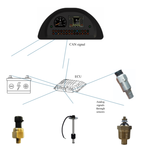
System Architecture for mixed signal-based instruments in vehicle

Why Vision-Based EOL Testing Is Essential for Modern Truck Clusters

Why Vision-Based EOL Testing Is Essential for Modern Truck Clusters

Why Vision-Based EOL Testing Is Essential for Modern Truck Clusters

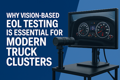
In the automotive industry to make the vehicle more reliable, the need for automatic inspection systems on production lines has increased. Hence, one of the important automated inspections is vision-based end of line testing for truck clusters.

What truck clusters have?

  • Multiple Telltale LEDs (Indicator tell tales, Warning Tell tales etc)
  • Display screens LCD/TFT (These display Odometer reading, Trip reading, Air pressure bars, DEF gauge, various tell tales etc)
  • Pointer based gauges (Speedometer gauge, RPM gauge, Engine temperature gauge, Fuel gauge)

What vision system can check?

  • LED presence and color
  • Correct Telltale shape
  • LCD/TFT digit cuts
  • Pointer positions and jerky movements.

How does a vision system work?

A vision system uses a camera to see the cluster and software to judge whether the cluster is OK.

  • The camera takes an image of the cluster (dial, pointer, LED, LCD etc).
  • The image is taken in a dark area where a camera is mounted at a fix position.
  • The software compares the captured image with a pre-teached master image and gives a decision OK or reject.

What are the parts of a vision system?

  • Industrial camera with lens to capture the image.
  • An enclosed chamber to create a dark area.
  • Industrial PC to run the software.
  • Mounting fixture for holding the cluster while testing.
  • PLC interface for providing inputs for cluster functioning.

Why is manual testing by humans not reliable for truck clusters?

  • Human eyes cannot maintain the same accuracy over time due to fatigue. There are more chances of error in human testing.
  • Even if the operators are fully skilled for testing they can miss minor defects such as LCD digit cut etc.
  • An operator cannot check multiple LEDs and check them one by one which increases the testing time.
  • There can be difference in judgement of two operators for the same cluster.

Vision system removes human dependency and ensures consistence testing.

What are the benefits of a vision-based system?

  • Vision systems never get tired, distracted, or inconsistent. 

Example: While checking telltale LEDs, a human operator may sometimes miss a defect, but the vision system will detect the defect repeatedly.

  • Vision systems are faster compared to manual inspection.

Example: While checking multiple telltale LEDs a operator will check them one by one but the vision system can check them together.

  • No need to rely on highly skilled manpower for visual judgment. 
  • Using the vision system will reduce the defects passing to the customer, resulting in customer satisfaction.
  • Using a vision system will reduce zero KM failures resulting is reduction in cost of quality and improving customer satisfaction.

What are the Limitations of vision-based System?

  • Vision setups are very expensive.
  • Cannot detect all electrical, mechanical and software defects such as fitment issues, Buzzer failure, Can communication errors etc.
  • Needs very accurate teaching of each variant.
  • Can give false OK and false rejections if teaching is not accurate.
  • Requires a dark area for placing the test part and camera.
  • Breakdown times are longer and difficult troubleshooting resulting in higher MTTR.

Challenges in testing pointer based gauges:

  • The pointer appears at different positions when viewed from different angles.This causes parallax error.
  • Some pointers are reflective due to which their edges become hidden.
  • Pointer has a dynamic behavior but the vision system used static images, this mismatch causes challenges in accurately detecting pointer positions.
  • The use of static images in vision system causes challenges in detecting jerky and sticky pointer movements.
  • When the camera captures the image of a moving pointer , there are chances of getting blur images causing false rejections.

What Softwares and technologies are used in Vision systems?

  • NI vision
  • Labview vision
  • Cognex vision Pro
  • Halcon machine vision software

Some technologies used are:

  • Optical character recognition
  • Color analysis
  • Edge detection
  • Pixel comparison

FAQs: EOL testing vs HIL testing

What does an EOL vision system check?

EOL mainly focus on:

  • Hardware defects
  • Display defects
  • LED/Telltales issues
  • Pointer alignment

EOL ensures cluster is defect free in hardware aspects before shipment.

What does a HIL(Hardware in loop) system check?

HIL focus on:

  • Software logic
  • Communication protocols (CAN)
  • Internal algorithms
  • Calibration checks.

HIL is used during development, validation and software release cycles.

Why is vision-based testing more suitable for high-volume production lines?

It enables inspection of several parameters simultaneously, such as LEDs, LCD segments, and pointer positions, among others, at very high speed. This makes them very ideal for mass production environments where consistency, speed, and accuracy are critical. Unlike manual operators, vision systems do not slow down over time, ensuring stable cycle times and higher throughput.

Can a vision-based system detect intermittent or temperature-dependent defects?

Although vision systems are great for detecting visual and appearance defects, some intermittent or temperature-dependent problems—like intermittent backlight flicker, thermal LCD defects, or pointer stiction at variable temperatures—may not get detected. In those cases, special endurance rigs or environmental chambers and HIL testers are needed along with the vision-based inspection.


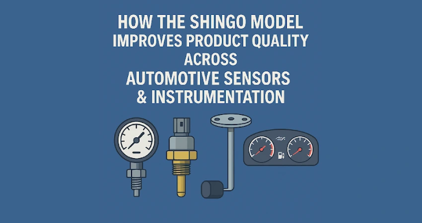
How Shingo Model Improves Product Quality Across Automotive Sensors & Instrumentation

How Shingo Model Improves Product Quality Across Automotive Sensors & Instrumentation

shingo-model-automotive-sensors-instrumentation

In most factory environments, product quality tends to be a department-level concern, typically that of QA or QC. But anyone who’s put in enough time on the shop floor knows the truth: quality is a result of the system, not a feature of a department. And that’s where the Shingo Model deviates. Instead of encouraging more inspection or stricter controls, the Shingo approach focuses on culture, behaviours and principles that guide toward reliable quality at the source.

In the last few years, especially as companies compete on speed, user experience, and reliability— Shingo techniques have become more timely than ever. They provide a disciplined but human-focused approach to scale quality without process overengineering. Here’s how they impact.

1. Quality starts with culture

One of the biggest epiphanies from the Shingo Model is that quality is not something technical systems can deliver. You can bring in poka-yoke, standard work, 5S or automation, but if they don’t believe in quality, they take no pride in keeping defects at bay, the gains remain superficial.

Shingo emphasizes Respect for Every Individual and Leading by Humility as core principles. The attention therefore moves away from finger pointing at operators to instead recruiting them. Where frontline teams feel appreciated, they give a damn about getting it right the first time.

For example, a team assembling automotive instrument clusters or calibrating pressure gauges often detects issues early when team culture encourages ownership. This one change by itself brings ownership and slashes rework.

2. It drives “quality at the source” rather than end-of-line policing

For many factories, end-of-line inspection is still heavily relied upon. It’s costly, inefficient and does not prevent defects – it only detects them.

Shingo methods emphasize quality at the source, that is,

  • Operators identify and fix issues on the fly.
  • Each step contains its own error checking.
  • Line teams halt production when anomalies arise.

That means instant correction, rather than batch-wise emergency alarm fighting. Over time, this discipline cuts down the need for inspection because the processes become intrinsically more reliable.

This approach is crucial in production lines manufacturing fuel level sensors, DEF sensors, analog gauges, electronic speedometers, RPM tachometers, or dashboard instrument clusters, where any defect can disrupt vehicle safety and customer trust.

3. Shingo principles backing continuous improvement that endures

Why most quality initiatives fail — because they fade. They begin with a fanfare, but after months, banners blur, audits are mundane, and the good old ways creep back in.

Shingo addresses this by encouraging three levels of improvement:

  • Cultural enablers
  • Continuous improvement
  • Enterprise alignment

Continuous improvement tools like Kaizen and value stream maps and PDCA and standard work provide structure, but it’s the cultural piece that sustains them. Shingo instructs that habits are powered by beliefs — and lasting change occurs when habits match those beliefs.

This is to say quality improvements no longer rely upon a handful of passionate and energetic leaders, it becomes institutionalized.</>

4. Shingo and Quality in Automotive Instrumentation

In industries such as automotive gauges, fuel level sensors, pressure gauges, instrument clusters, and digital speedometer clusters, Shingo principles become even more critical. Products like pressure sensors, coolant temperature sensors, electronic tachometers, fuel indicators, and dashboard instrument clusters require consistent manufacturing discipline because even a minor variation can affect vehicle performance. By promoting stable processes and quality at the source, the Shingo Model ensures reliability across components such as fuel level sensors, speed sensors, engine temperature gauges, and modern digital instrument clusters used in trucks, buses and EVs.4. It generates deterministic and reliable workflows

In the end, good quality comes from stable processes. Shingo assists organizations in discovering the underlying instability causes – such as:</>

  • Variation in work methods
  • Poorly maintained equipment
  • Lack of clear standards
  • Frequent changeovers
  • Overburdened operators

Applying Shingo principles gives teams the tools to organically shift towards

  • Clear standard work
  • Visual controls
  • Mistake-proofing
  • Flow and pull systems
  • Preventive maintenance

Once processes are humming, defects fall almost of their own accord.

5. Respect-Based Problem Resolution Improves Products

One of the Shingo philosophy’s strongest pillars is that the doers know the work best. This is devastatingly powerful for quality improvement.

Rather than having the managers or engineers remotely attempt to infer the root cause, the operators are engaged in

  • Problem definition
  • Suggesting countermeasures
  • Testing solutions
  • Standardizing improvements

This ‘bottom-up wisdom’ results in more workable solutions and greater buy-in. They’re fixed for good — not patched for now.

6. It maps excellence to company mission

Most quality defects occur because teams are pursuing local KPIs – output, cost, or speed – instead of doing things right.

Shingo emphasizes alignment by ensuring that every employee knows the mission: to generate value for the customer. When purpose is the anchor, decisions organically weigh quality, cost and delivery in equilibrium rather than trading one off against the other.

A line leader could say,

We could run the line harder, but if quality will suffer, we’ll clear the bottleneck first.”

This mindset shift safeguards long-term brand equity.

7. Shingo motivates going to the Gemba

Good issues rarely get resolved in board rooms. Shingo encourages leaders to conduct Gemba walks — to observe processes firsthand and to mingle respectfully with workers. When leaders are visible, accessible, and inquisitive — not critical — quality impediments rise to the surface rapidly.

You start hearing things like:

The fixture’s a little loose, so sometimes alignment gets off,

or

We bypass this during rush hour because the tool clogs.

These insights barely land on any quality report but are crucial in preventing defects.

Final Thoughts

Quality improvement isn’t about recruiting ever more inspectors, or honing the specification, or stacking on audits. The Shingo methods make us remember that quality is people, process and purpose aligned. By instilling a culture of respect for people, promoting kaizen, and orienting everyone towards the customer, Shingo gives the organization a powerful sustainable process for delivering world-class quality. Whether you manage a single line or a whole plant, Shingo principles can transform quality from a struggle into an organic side effect of how people work every day.


Mechanical Temperature Gauge Benefits & Why It’s Still a Popular Choice around people

Mechanical Temperature Gauge Benefits & Why It’s Still a Popular Choice around people

mechanical-temperature-gauges-still-popular

Introduction to temperature gauges

The temperature gauge is one of the most important gauges to denote the condition of internal combustion.

The history of the temperature gauge

The humble mechanical temperature gauge, which did its job over several decades, lost its prime position to the electrical air core gauge, which was used in combination with a temperature sensor. There have been many technology upgrades since then, and the air core itself was replaced by the stepper motor inside the gauge. The stepper motor was controlled by a microcontroller, so it became possible to manipulate the pointer movement in a far more sophisticated manner. You could increase or decrease damping, make the scale non linear, create a dead zone too, to avoid alarming the driver. It was a matter of time before digital technology stepped in, and the input to the temperature gauge was digital, the most common being J1939 protocol based inputs. And finally you also had a bar graph or even virtual.

It seemed the mechanical temperature would die a natural death, since it was a low technology product. It was difficult to install, readings could be affected by ambient temperature, required a lot of skill to manufacture ( and those skills were not easily available any longer), failure levels were higher than solid state products, etc.

However, it is still very around, albeit as a niche product. In certain applications it is still the most suitable product and simply has no substitute.

How does a mechanical temperature gauge differ from a home thermometer ?

Before we go there, there is a little bit about the design and principle of operation of mechanical temperature gauges. Basically the mechanical temperature gauge is similar in principle to the mercury thermometer we used ( or still use) to measure our body temperature or fever ! the main differences are:

  • There is a dial instead of a calibrated glass tube as the readout
  • The temperature range is generally 40-120C instead of 95-110F ; and as a result, does not use mercury as a medium
  • it is significantly longer and allows the dial to be mounted in front of the driver even though the engine / radiator is far
  • it is far more robust

What are the construction details of a mechanical temperature gauge ?

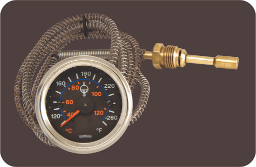
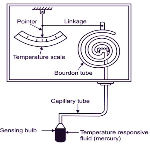
Mechanical temperature gauges basically consist of a sealed capillary containing a medium inside, on one side of which there is a sensing bulb and on the other side is the coiled bourdon tube.

The bulb is inserted into the radiator (or other suitable receptacle) from where it senses the temperature to be measured. The volume of the bulb is kept high, so that when it expands ( as the temperature increases), it creates an internal pressure in the capillary which leads to the bourdon spring opening out and moving the pointer.

Two types of used mediums are commonly used, Either and xylene . IIL is perhaps the only company in the world making xylene based mechanical temperature gauges.

  1. xylene has a boiling point of 140 °C ; so it stays in the liquid form over its working range and hence lends itself very nicely to a linear scale dial. In fact sometimes it is even used for +200°C gauges, and due to the xylene being pressurised, it stays in the liquid stage until then too.
  2. Ether has a boiling point of about 34°C, so it stays in a vapour state for most of its range. Its expansion is exponential as the temperature rises, so the dials of an ether filled gauges are nonlinear.

Why is the mechanical temperature gauge still being used?

No Power Supply needed

Mechanical temperature gauges are completely self-operating devices. Because of this advantage, industries prefer mechanical temperature gauges over digital alternatives, especially for critical safety monitoring. For example, in a diesel engine cooling system or a boiler, a mechanical temperature gauge continues to show accurate readings even during power failures — ensuring operators can make decisions quickly.

Accurate and Consistent Readings

Mechanical temperature gauges are a single unit, so have good accuracy under most conditions, and maintain their consistency over a long time. precision, well-calibrated Bourdon tubes.

Cost-Effectiveness

Mechanical temperature gauges are more economical to purchase and maintain. They require no wiring, signal transmitters, or controllers. Once installed, they operate for years without needing spare parts or batteries.

Simple constructions

Many operators also prefer mechanical gauges because they are direct-reading instruments — the pointer movement directly represents the temperature change. There’s no risk of software malfunction, sensor lag, or digital display error, making them more trustworthy in critical safety systems.

Easy Installation

Mechanical temperature gauges are easy to install and require minimal setup. They can be mounted directly on the equipment or remotely using capillary tubes.

FAQ:

Why are xylene filled mechanical temperature gauges so robust?

Xylene filled mechanical temperature gauges use a microbore copper caplliray whose bore is only 0.1mm, the size of a human hair. However its wall thickness is 4X of the bore. In addition, this capillary is protected by a multistrand stainless steel sheathing. So, even if an elephant were to step on it, the capillary bore would not get compressed. We at IIL go so far as to say that the only way to make the capillary fail is to physically cut the sheathed capillary using a hacksaw.


Odometer vs Speedometer: Key Differences that all drivers should know

Odometer vs Speedometer: Key Differences that all drivers should know

odometer

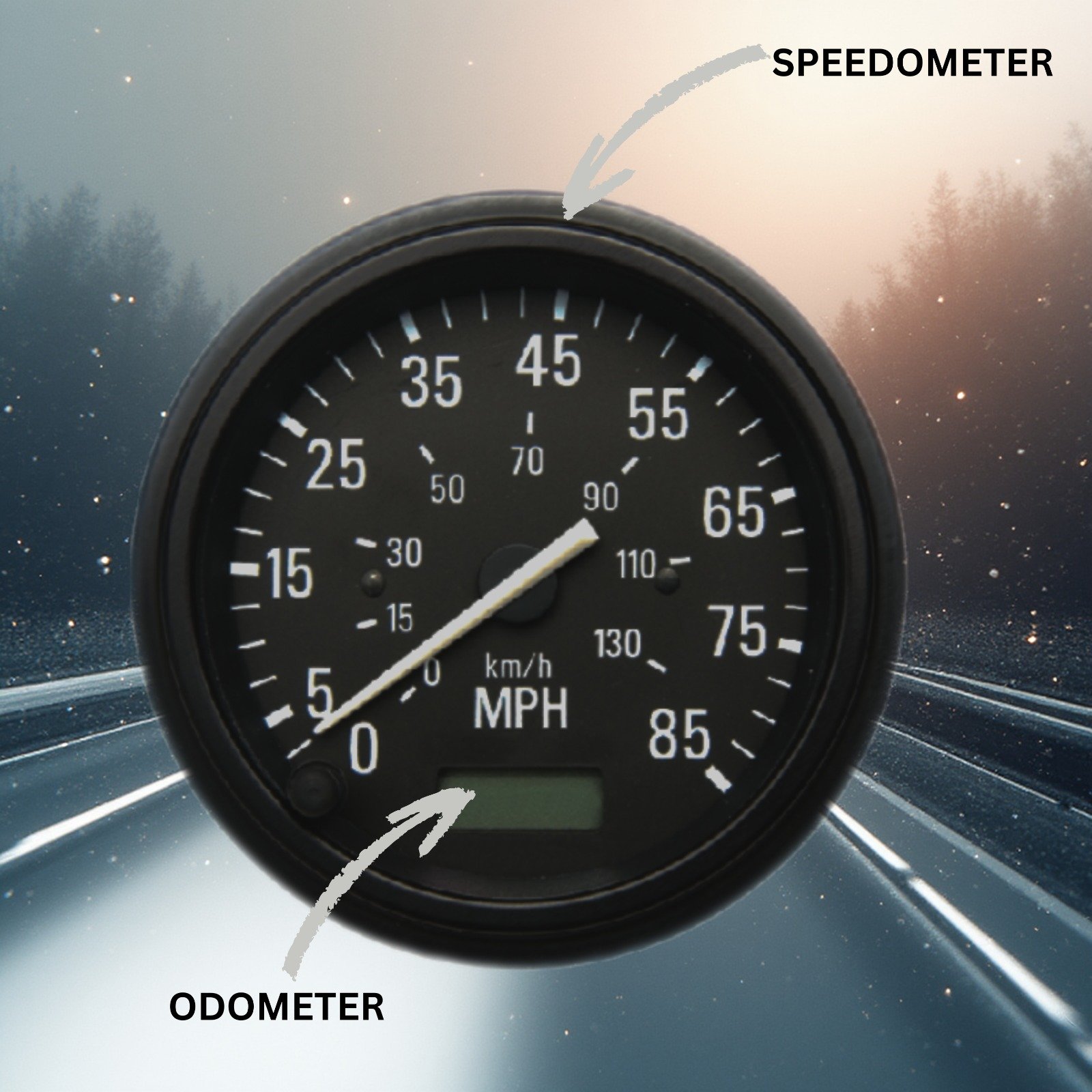
What is a speedometer and why is a speedometer so important?

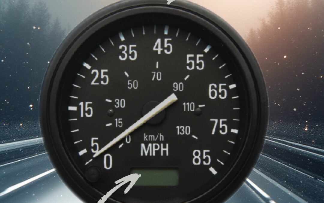
A speedometer is an instrument that displays the instantaneous speed of a vehicle, or to be more precise, the vehicle’s wheels.

Speedometers inform the user about how fast the vehicle is traveling at any given point. This can be in kilometers per hour (km/h) or miles per hour (mph).

A speedometer is a very important instrument in any vehicle, since drivers are supposed to follow speed limits while driving, and so they need to know the vehicle speed accurately.

ggg

Odometer vs Speedometer: How They Work, and How OEMs Choose the Right One

A speedometer and an odometer sit side by side on almost every vehicle dashboard, but they answer two different questions. The speedometer tells you how fast the vehicle is moving right now. The odometer tells you how far it has travelled in total. For a driver, that distinction matters for safety and for resale value. For an OEM engineering or procurement team, it also decides which sensor inputs, calibration method, and display technology to specify when sourcing an instrument cluster. This guide covers both angles.

Odometer vs Speedometer: The Difference in One Line

A speedometer measures a vehicle’s current speed, usually derived from wheel RPM; an odometer measures the total distance travelled, calculated by counting wheel rotations over time. One is a live reading that changes constantly; the other is a cumulative total that only ever increases.

What Is a Speedometer and How Does It Work?

A speedometer displays the instantaneous speed of a vehicle — strictly speaking, the rotational speed of its wheels, converted into a familiar unit like km/h or mph. Drivers rely on it to stay within speed limits and to gauge how the vehicle is handling in real time.

By design, most speedometers are calibrated to read slightly higher than true road speed — typically within about ±2% of full scale — as a built-in margin that discourages unintentional overspeeding. The actual accuracy of that reading depends on more than the instrument itself: wheel RPM passes through gears and pulleys before it reaches the speedometer, and any deviation in those ratios from the original calibration shows up as reading error.

What Is an Odometer, and What Is a Trip Odometer?

An odometer is a separate instrument — even though it usually shares a housing with the speedometer — that totals the distance a vehicle has covered over its lifetime, shown in kilometres or miles. A trip odometer does the same job over a shorter, driver-defined window: it can be reset at will, which is why many vehicles offer two of them, one for daily driving and one reserved for tracking a specific journey, fuel-fill interval, or maintenance cycle.

Odometer data isn’t just a dashboard number. It’s the reference point for warranty tracking, scheduled-service intervals, fuel-efficiency calculations, and resale valuation — which is exactly why OEMs treat odometer accuracy and tamper-resistance as a specification, not an afterthought.

Why Odometer and Speedometer Readings Matter Beyond the Dashboard

For an individual driver, these two readings support safe driving and basic maintenance planning. For a fleet operator or an OEM building the vehicle in the first place, they carry more weight: odometer data underpins warranty claims and scheduled-maintenance triggers, speed data feeds into driver-behaviour and safety programs, and both are increasingly logged over CAN/J1939 for telematics and compliance reporting rather than just displayed on a dial.

Mechanical vs Electronic Odometers and Speedometers

  • Mechanical: driven by a flexible rotating cable connected to the gearbox, moving a pointer for speed and rotating number wheels for distance. Simple, robust, and largely obsolete in new vehicle programs.
  • Electronic: driven by sensor signals — analog or CAN-based — that are processed and used to drive either a stepper-motor/air-core pointer or a fully digital LCD readout. This is the standard for virtually all new commercial and passenger vehicle programs today.

What Feeds an Electronic Speedometer or Odometer?

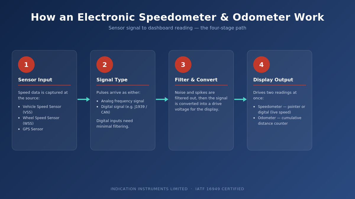
Electronic units typically take their input from one of three sensors and switches, either directly or through the vehicle’s ECU:

  • Vehicle Speed Sensor (VSS) — mounted at the gearbox or transmission output
  • Wheel Speed Sensor (WSS) — the same sensor family used for ABS and traction control
  • GPS Sensor — increasingly common where wheel-based sensing is unreliable or unavailable

These inputs may arrive as raw analog pulses or as digital signals such as J1939, which require far less filtering and generally deliver higher accuracy.

Speedometer vs Tachometer: Not the Same Instrument

It’s a common mix-up: a speedometer measures how fast the vehicle’s wheels are turning, converted to road speed; a tachometer measures how fast the engine’s crankshaft is turning, in RPM. The two numbers move together but are never identical, because gearbox and differential ratios sit between the engine and the wheels. If you’re specifying or troubleshooting engine-speed instrumentation specifically, see our companion guide: What Is a Tachometer and How Does It Work?

How Speedometers and Odometers Are Calibrated

For engineering teams specifying calibration parameters, the relationship between sensor pulses and displayed speed follows a fixed formula:

Input frequency at a given speed: f = (pulses per km × speed in km/h) ÷ 3600

Pulses per kilometre are derived from the sensor’s mechanical relationship to the wheel: Np/km = (gear ratio × sensor pulses per revolution × 1000) ÷ wheel circumference (m)

Example: with a gear ratio of 4, 8 pulses per revolution, and a 2 m wheel circumference, that works out to 16,000 pulses per kilometre.

Odometer distance is then simply total pulses received divided by pulses-per-kilometre, with digital displays typically incrementing in fixed steps (e.g. every 0.1 km) based on that same pulse count.

Choosing Speedometer & Odometer Technology for Your Vehicle Program

If you’re specifying instrumentation for a new vehicle platform rather than just troubleshooting one, the real decisions come down to three trade-offs:

  • Sensor choice: GPS is highly accurate in open terrain but can lose signal in tunnels or dense cover; a Vehicle Speed Sensor is compact and reliable but sensitive to tyre-size or gear-ratio changes; a Wheel Speed Sensor gives the most precise, wheel-specific data and doubles up with ABS/traction systems, but needs clean operating conditions.
  • Actuation: stepper-motor movements offer higher accuracy and self-test capability at a higher cost; air-core movements respond faster and cost less, at a small trade-off in long-term accuracy.
  • Display: analog pointer displays are easier to read at a glance during dynamic driving; digital 7-segment displays are more precise and legible in low light, with no parallax error.

Indication Instruments Limited designs and manufactures both mechanical and fully electronic speedometer and odometer instrumentation — for trucks, buses, tractors, construction equipment, and specialty vehicles — under IATF 16949 quality standards, for OEM programs across India and export markets. Explore our full instrument cluster range or talk to our engineering team about a custom specification.

Frequently Asked Questions

What does an odometer measure?

The total distance a vehicle has travelled over its lifetime (or since a trip odometer was last reset), measured in kilometres or miles by counting wheel rotations.

What does a speedometer measure?

The vehicle’s current speed, derived from the rotational speed of the wheels and converted to km/h or mph.

What distinguishes a speedometer from a tachometer?

A speedometer measures vehicle wheel RPM and converts it to road speed; a tachometer measures engine RPM directly. The two differ because of gearbox and differential ratios between the engine and the wheels.

How does an electronic speedometer or odometer work?

It takes analog or digital pulses from a speed sensor, filters the signal, and uses it to drive either a stepper-motor/air-core pointer or a digital display. Digital inputs such as J1939 need minimal filtering and are typically more accurate.

Why do tractors and off-road vehicles have speedometers if road speed limits don’t apply to them?

For operator convenience and safety — consistent speed matters for tasks like ploughing, seeding, or towing, and many tractors are also road-legal for limited transport between farms, where speed indication is expected.

What is the advantage of a stepper-motor speedometer over an air-core one?

Stepper motors offer higher accuracy and built-in self-test capability; air-core designs respond faster to changes and cost less to produce.

How are speedometers and odometers calibrated?

Through a fixed relationship between sensor pulses per kilometre and vehicle speed — see the calibration formulas above. Gear ratio, sensor pulses per revolution, and wheel circumference all factor into the calculation.

What’s the relationship between speed and distance?

Distance equals speed multiplied by time. At constant speed, the odometer’s cumulative reading rises in direct proportion to the speedometer’s instantaneous reading over that period.